I won’t spend any time introducing this truck, or its North-American maker.1 If you want to know more about the later, who genuinely and unironically identifies as “Moe and Mrs. Moe,” watch a few seconds of one of their YouTube videos (Moe, it doesn’t matter which side of the axle you mount them!2), and don’t let me impose my own prejudices on you.
This is how I will go about this: I will build a model of the truck, which requires that you, dear reader, make some effort and come meet me halfway, because the model will truly be very abstract. It will help us however see the constraints under which the truck is meant to operate. At that point, it will become apparent that the constraints make it physically impossible for the truck to turn. Buckle up.
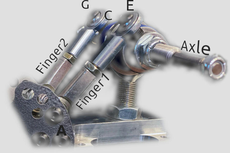
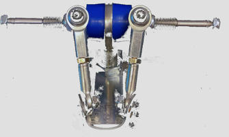
The truck is essentially supposed to be three intersecting spheres. “Finger1” is fixed on one end “A” on the base-plate and on the other end “E” it is fixed on the axle. Let’s arbitrarily assume that the base-plate is the static part of this whole thing (as far we, the observers, are concerned). Then point “E” is free to rotate around “A” in any direction it wants. So, the first sphere would have center “A” and radius “AE,” or simply put, the length of “Finger1.” The same exact thing, mirrored for the other finger gives us the second sphere. We also have to fix the axle somewhere. We fix the axle on point “C,” i.e., the middle lower point of the base-plate (where the big spherical bearing is). If we assume the fingers are attached on the axle and they are not meant to slide on it, then points “E” and “G” have, and can only ever have, the same distance from “C”. So, the third sphere has center “C” and radius “CE”=”CG.”
Are you with me? One more step. The section between these three spheres (i.e., the two circles on the image on the right/up) are the only locations on which the free points “E” and “G” can exist. So far, so good. But also, there must be a straight line between “E”, “G” and “C.” Simply put, the axle must go through all three of these points, because it is not elastic. Well, unfortunately this configuration is physically impossible. As soon as the axle turns, any possibility for a single line containing these points disappears. Why? Because. Nobody ever said there could be a line to solve this equation and there isn’t one. The two circles do not belong on the same plane. How could a line go through them both? This would only be possible if “A” and “A’ ” were the same point.3
There’s also something you could try yourself at home with three toothpicks. Place them so that they are like a triangle, but with one of the three corners not actually a corner but a bit open, to represent the points where the fingers are attached to the base plate (a trapeze). Now rotate one of the two fingers and make the axle-toothpick follow it, like the truck would if it were turning. You can now see that the axle has to come closer to the base-plate. But it can’t, because it’s fixed with a bearing in the middle, remember?
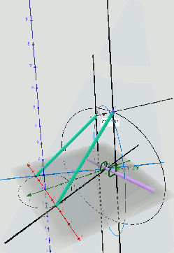
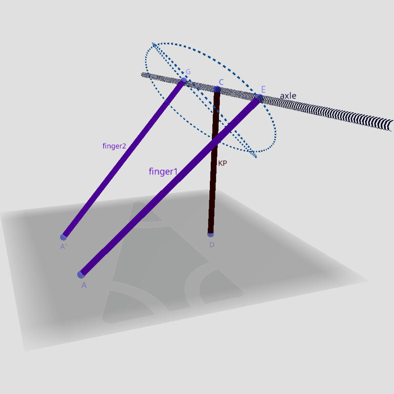
One last note to dispel possible doubt caused by the fingers not looking like they intersect the axle on the actual truck: it is unnecessary to represent that part more accurately on a model. What matters is only their ends, on the base-plate (“A” and “A'”) and on the hanger (“E and “G”), regardless of their shape (or thickness, or color, etc) in between. The reason? All the joints that are not spherical bearings are supposed to be rigid/static, therefore the two purple segments you see (on image 1) are supposed to remain constant in length. That said, for you, the most skeptical of readers, I’ve also prepared a more analytical model, but I really need your full attention on this, and it’s not going to be too easy to follow. Stick with me please (if you feel you need further proof). On image 3 on the right, you see all of the parts that consist the truck, as I indicated them in the photo above. The green segments are the fingers, the purple line is the axle, the two vertical black lines are the collars that fix the fingers on the axle. The gray plane is simply the plane defined by the three spherical bearings (at A, A’ and C in the photo). On this model however, I made sure to keep the fingers and the collars constant in length, as well as the distance between all three spherical bearings of the base-plate, as they all necessarily are in reality. But the distance between each spherical of the two fingers and the axle still must vary, while the truck turns, because of the reason I explained above. How can this happen? This can only happen if the angle, that the collars form with the roots of the fingers, changes constantly (angle β on image 3). Yes, the fingers also connect to the collars with spherical bearings, therefore that could make the required varying β possible, but do the collars also connect with spherical bearings on the axle? No, they are tightly fixed on it.4 Yes, indeed: the collars just rub on the axle the whole time, which explains why the trucks don’t turn freely, even without bushings.5 So, don’t tight the collars too much, or the trucks won’t turn and also you will wear them out too fast; don’t let them too loose, or the trucks will just turn whenever they like and you will die. And keep tightening them after every ride, for your own health. That’ll be $595.00,6 please!
That’s it. I hope you enjoyed this one. If you followed the argument, you probably understood that this truck can’t exist without axle and/or fingers and/or collars that have some sort of elasticity to change their length, shape, or curvature. You might wonder how come the trucks still kind of work. Well, I do too, and my guess is as good as yours. Mine, for the record, is that the tolerances are not that low. Some squeeze here, some slide there, some bendy bit in between and a few looser bearings will absorb some of the stress from the bolts that hold the collars in place, and keep the truck looking like it pretends to be.5 It’s sort of like watching steam-punk cartoons, fascinated by machines that look kinda cool (if that’s your thing), but then realizing the machines couldn’t possibly exist, because they violate the laws of physics and logic. And then the magic disappears. It’s a mere illusion, dear reader. No one has ever managed to employ two turning axes on one axle (I’m looking at you, Carver C7 and assorted rip-offs), controlled, no less, by the same force.7 It’s just logically impossible.
If, on the other hand, you didn’t follow the argument, but you are nevertheless convinced it was wrong, please add at least one swearword in your passionate message, so that the spam filter catches it without me having to manually ignore you. Thanks!
The two photos that I used/edited for the article were sourced from the maker’s website (stoogeraceboards.com).
I’m immensely grateful for the feedback from three friends of the blog, Michael Hollingsworth, Joren Miner and Friedmar Richter (aka Bogbugboards), without whose generous and truly stimulating input, vehement but fair critique and, I’ll admit, sharper intellect and deeper knowledge, I wouldn’t have been able to complete this article.
1. I’m still not sure to which market they’re supposed to cater, or whether they are actually popular in it. But I thought modeling them, to show whether they could work or not, was an interesting challenge and a skate-geometry-related topic for my blog. Thanks goes to Andreas Tauber, who pointed out these trucks to me, almost a year before I actually sat down to write this post.
2. Indeed, you could make any shape of fingers and have them spiral around the axle 5 times before they reach it, wherever they may reach it, and it still wouldn’t matter, as long as they’re rigid. Would look way cooler though.
(For the record, in case the video is taken down, Moe says “[00:24] the project is, we’re going to take a 35° angle and we’re going to show you how to roll that over into a 10° [by changing where the fingers are mounted!] [01:15] Put the rods [fingers] on the bottom and for the rear [truck] what it does is, the less steer you have in the rear the more stable your truck becomes. 30° would be a pretty carvey rear truck with the “3-link.” You still have steer with a 10°, it’s just better for the high speeds and the downhill stuff.“)
3. In which case (and only then, Moe!) the axle could move along its aforementioned constraints. But then the truck wouldn’t be anything special and Moe couldn’t really ask 600$ (see also below).
4. Just as they should, I might add, otherwise the truck would become impossibly unstable, turning without the rider even having to first tilt the deck. Safety above all, with Stooge Raceboards!
5. Thanks to Ben Edelstein, who pointed me to this video from those cool skate-geeks, we can also see footage of this truck having trouble turning, without any bushings muddying things up. Unfortunately, these youtubers misdiagnosed the problem there, or at least forgot to talk about the most important problem. In any case, I can’t recommend their channel enough.
6. Checked mid-October 2022 on the truck maker’s homepage. Only pairs of the trucks were available at this point.
7. Here, I imply the central bushings. At least on the C7 et al the two axes are controlled by two different sets of bushings and/or springs. Still sketchy, but not extremely dumb.

Great article. Looks like you need to acquaint yourself with the exploding esk8 scene though. eSk8.news is a thriving community where Moe is held in high regard.
#too_posh_to_push
Thank you, Leon! And thanks for the heads up! I will keep my eye open, there must be lots of experimenting with design there. As for Moe and Missus Moe, well, I wouldn’t assume they were trying to cheat the market (like I believe Major Arc did), I believe they genuinely thought the truck was ok. But they’re not the geniuses they probably sell themselves as either…
I love the hashtag!:)
These trucks are real, they not only work but they work with precision. There is no slop like with TKP or RKP trucks. The older designs rely on the bushing to hold the bushing cup centered and often has play in this joint. The SRB 3- link truck has a center heim joint with tight tolerances. To fix the model above add another axis to account for the lean angle of the board. The axles move in two planes at once. Both forward and backward and also up and down simultaneously. It changes the angles of the triangles made by the board, the radius rods and the height of the axle from the plane of the board. If you are in the Seattle area I can give you a proper demonstration with a board that has SRB 3-link trucks that haven’t been taken apart and pieces left out like in the video you cited. If you are not in the Seattle area go to stooge TV for tech tip videos.
Thanks Joey! I’m not near Seattle, but that’s super nice of you. You, please, try the toothpicks thing, ok?
I read this post, and appreciate the in depth analysis, working to explain thouroughly, and questioning/thinking about this design when most people would just accept it blindly. No matter how correct, that’s what this world needs more of! If incorrect in some aspect, that’s how innovation and engineering works best, then to find those, and analyze from there.
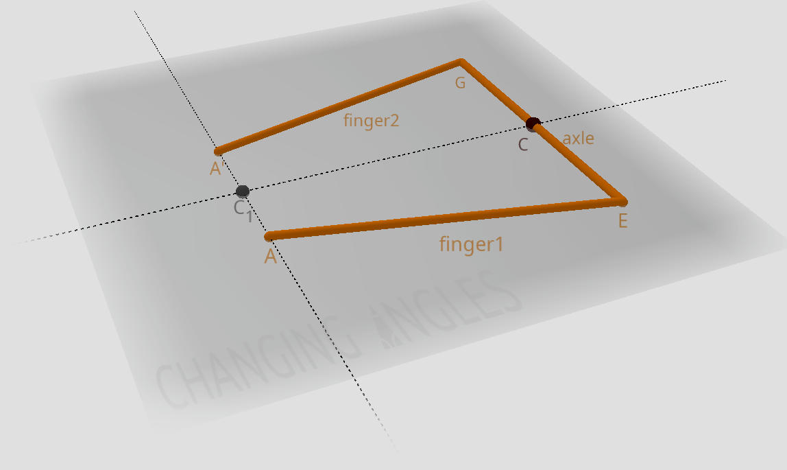
With that said, Joey is correct. With the last image (the orange lines on gray grid one), take the axle line (G – E) and rotate it around (C-C1), not on the gray plane, but so point G lifts off the plane, and point C goes below the plane.
Because of the two support ‘fingers’, it will still rotate, but the axis of rotation for the axle will move increasingly the more the axle itself is rotated around that axis, with that axis going from resting on the plane, to moving towards being perpendicular against the plane.
This geometry and path is actually extremely similar to rkp trucks already, if you draw a line from the axle/wheels to the pivot cup on the baseplate (not the bushings and kingpin pivot, of course)
This Stooge design instead has those fixed lines (the fingers) not meeting at the baseplate, but virtually meeting well past it, changing the “leaning vs turn” relationship to be less linear, with overall greater maximum turn, with less turn at first.
Hope this helps clarify. If it would be helpful, I could make a quick animation of this in Blender3d. Thanks!
Thanks for the comment! You are quite further ahead than most readers, I am glad. But, after you imagined the thought experiment with the toothpicks (i assume you meant E and G; C would ideally remain fixed on the same plane), did it not then strike you as obvious that C and C1 must necessarily come closer? CC1 changes length during the rotation. 😉 See? Tell me if you see it or not, please. And if you insist, then, yes, please model it for me and the readers.
„there must be a straight line between “E”, “G” and “C.” Simply put, the axle must go through all three of these points, because it is not elastic. “
I have been studying how these work and I believe this assumption is incorrect.
the points “E”, “G” and “C” effectively form a triangle with point „C“ anchoring that triangle to the baseplate.The key thing here is that this allows the main axle to roll, allowing the connecting point „A“ on the baseplate to change distance from the axle as it moves.
Imagine your purple model, but as you turn the hanger the two purple links can get slightly longer (but must still be equal).
Wait. The axle does not roll anywhere. It stays mounted on C. What are you saying? What is moving while the truck turns? Eager for your response on this.
E and G, for simplicity, can be sketched right on the axle on a model, since the fingers and their mounting bolts etc on the axle are rigid, not sliding or moving (at least not intentionally). I explained that extensively in the text (e.g. look for “to dispel doubt…“). Does it matter, you think, what shape the fingers have?
I could be wrong, but it appears as if the points where the linkages connect to the axle are on a rotating collar/bearing. If this is the case, when the axle is turned so that point E moves toward point A, the collar will rotate so that point E is now closer to point A on the X-axis but further away on the Y-axis. The opposite is true of finger2. Point G will move further away from point A on the X-axis but closer on the Y-axis. This allows for the axle to turn while keeping finger1 and finger2 the same length. Once again, I could be wrong but this would explain how this system is able to function. It might be easier to see what I assume to be a bearing in this image. https://esk8-news-objects.s3.dualstack.us-east-1.amazonaws.com/uploads/optimized/3X/f/6/f6ea1f0602f6b36c10e941c477a86f5b85a6fdec_2_500x500.jpeg
For some clarification, the X-axis is the distance horizontally between A and E and the Y-axis is the distance vertically between A and E.
Thanks for the comment!
If that’s the case, then yes, it would be possible. Is it though? (And how would the axle not turn when the deck doesn’t tilt?) Eager for your response.